 English
-
 Español
-
 Português
-
 Portugiesisch
-
 Français
-
 日本語
日本語
-
 Български
-
 한국어
한국어
-
 Türkçe
-
 Nederlands
-
 English
-
 Eesti
Eesti
-
 Suomi
Suomi
-
 বাঙ্গালি
-
 беларуская
-
 Ελληνικά
-
 Kreyòl ayisyen
-
 עִברִית
-
 हिन्दी
-
 Magyar
-
 íslenskur
-
 Gaeilge
-
 italiano
-
 Hrvatski
-
 Latinus
-
 latviski
-
 Melayu
-
 Malti
Malti
-
 Монгол
-
 မြန်မာ
-
 فارسی
فارسی
-
 Polski
-
 عربي
عربي
-
 Română
-
 русский
-
 slovenský
-
 Slovenščina
-
 Afrikaans
-
 svenska
-
 dansk
dansk
-
 український
-
 o'zbek
-
 Cymraeg
-
Zulu
-
 Tiếng Việt
-
 bosanski
-
 Deutsch
-
 eesti keel
-
 ไทย
ไทย

USB PD Quick Charging Power Negotiation
Thu Sep 07 15:27:13 CST 2023
USB PD Quick Charging Power Negotiation
What is USB PD quick charging technology?
USB PD fast charging technology is a technology for fast charging of USB devices through USB ports.
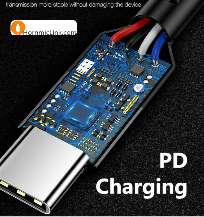
Due to the development of USB technology, especially the USB TYPE-C interface is widely used, based on the USB TYPE-C interface USB PD fast charging technology is becoming more and more mainstream.
Which devices can be charged with the USB-C connector?
● Can charge our mobile phones;
● Can charge our laptops;
● Can allow laptops to charge our mobile phones through the TYPE-C port;
● It can charge tablets;
● Can charge various devices with USB ports...
As you can see from the applications above, any device with a USB-C port can be powered. Later, with the application of USB4's more high-speed transmission specification, TYPE-C based DP interface monitors are also applicable.
Power negotiation of PD fast charging streams for USB-C
USB PD fast charging technology can be used to charge a variety of USB interface devices, but there is a problem is that the power supply voltage of these devices is not the same ah. Like the laptop interface is generally 20V, while the mobile phone is generally 5V power supply, so direct use will not be due to the voltage of the problem caused by charging or too high a voltage to the electronic equipment to be broken?
The answer is no.
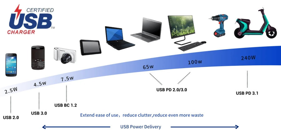
USB PD fast charging technology provides the ability to charge at four voltage sizes, including 5V/9V/15V/20V. For 5V, 9V and 15V, the maximum current is 3A, and in the 20V configuration, if the cable is ordinary, the maximum permissible output is 20V/3A, i.e., 60 W. If a specially customised cable containing an electronic tag is used, the corresponding figure can be scaled up to 20V/ 5A, i.e., 100 W. If a specially customised cable containing an electronic tag is used, the corresponding figures can be scaled up to 20V/ 5A, i.e., 100 W. 5A i.e. 100W.
The USB PD fast charging connection needs to power the device is the PD adapter, which is a charger capable of outputting four voltage specifications. It is like a transformer, divided into four gears, when the need for that gear power supply, the power supply voltage will be adjusted, but this adjustment process is through the PD power supply protocol "negotiation" out.
This is like a USB device is accessed through the PD power supply specification to tell the host, I want the voltage is a few volts and a few amps, you give this power supply on the good. The host receives the request and replies, "Okay, I'll power you with the power supply you need." This communication process is achieved through the CC pin in the TYPE-C interface, and through the VBUS pin in the USB 2.0 specification.
Power supply negotiation for USB-C ports
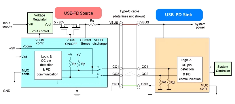
USB-PD power supply is divided by supply relationship:
● USB PD Source charging side, which provides power;
● USB PD SINK device side, receiving power.
Once the cable connection has been established, the SOP communication of the PD protocol starts on the CC line to select the specifications for the power transfer: the device side will ask the charging side for the power configuration parameters (different bus voltage and current data) that it is able to provide. Since the device-side demand for power is often related to the system on the charging side (e.g., a battery charger), the embedded system controller on the device-side will need to first communicate with the PD controller on the charging side to determine the appropriate specifications.
The communication between the Sink side and the Source side on the CC line looks like the following process.
1. The device side requests the capability data of the charging side.
2. The charging side provides its capability data information.
3. The device selects the appropriate power configuration parameters from the capacity data information provided by the charging side and sends the appropriate request.
4. The charging terminal accepts the request and modifies the bus voltage to the corresponding parameter. The current consumption at the device side is kept as small as possible during the bus voltage change. The charging terminal raises the bus voltage according to a defined voltage increase rate.
5. After the bus voltage reaches its final value, the charging terminal waits for the bus voltage to stabilise before sending out a power ready signal. At this point, the device end can increase its current draw.
6. The same communication process occurs when the device side wants the bus voltage to decrease. During the bus voltage drop, the charging terminal activates a shunt circuit that rapidly reduces the bus voltage through active bus discharging. After reaching the nominal value, the charging terminal waits a slightly longer period of time for the bus voltage to stabilise before sending a power ready signal.
This method of communication ensures that any power changes on the bus fall within the capabilities of the source and sink, avoiding uncontrollable conditions. When the Type-C cable connection is disconnected, the power on the bus is also switched off and any new connection is detected as a cable connection and the voltage is always at 5V, which avoids high voltages going from one device to another when the cable is switched on.
The communication between the DFP and the UFP is as follows:
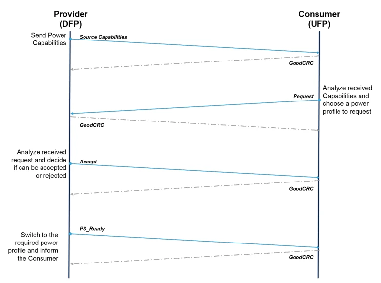
● The source (DFP) schedules a Source_Capabilities message with its available power profile.
● The receiver (UFP) analyses this message and sends a request for the profile that best meets its requirements. The source can accept or reject this request based on the power omissions at the time. If the source can accept the request, it switches to the desired power profile and sends a PS_Ready message to the receiver.
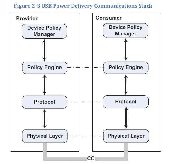
7_USB_Power_Delivery_Communications_Stack
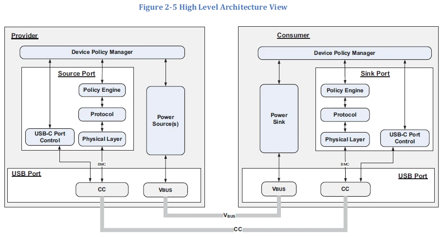
9_PD-Provider-Consumer High Level Architecture
By now, basically you are clear about the specifications of the PD adapter and how it works. Firstly, it contains several output specifications; secondly, it communicates with the device side through the Type-C cable, identifies the device side and converts the output specifications reasonably; so it can charge laptops as well as mobile phones.
![]()
By HornmicLink_Bob Kuo @230907 15:30
